We recently published a blog post on the results of a comparison test of Kafka throughput via Internet VPN versus PacketFabric Virtual Cloud Router private connectivity. This is a companion post that spells out how you can run this test for yourself.
Prerequisites and assumptions
You will need an Azure VNET and AWS VPC to run these tests. We will not be giving step-by-step instructions for creating an Azure VNET or AWS VPC in this document, as these are well documented by both vendors.
Assumption1
You will need 2 VMs on Azure. “Standard F8s_v2 (8 vcpus, 16 GiB memory)” instances were used for this demo. These are used to create:
- ETL pipeline VM
- iperf3 VM
Assumption2
You have access to a PacketFabric Portal account. Feel free to visit us at packetfabric.com to learn more.
Assumption3
We will implement the setup used in AWS “Managed Streaming for Kafka Tutorial.
Implement Kafka tutorial configurations on AWS
Steps from AWS Managed Streaming for Kafka Tutorial:
- Step 1: Create a VPC for Your MSK Cluster
- Step 2: Enable High Availability and Fault Tolerance
- Step 3: Create an Amazon MSK Cluster
- Step 4: Create a Client Machine
- Step 5: Create a Topic
- Step 6: Produce and Consume Data
For reference, the MSK Tutorial creates an “m5 large” instance for the cluster.
| IMPORTANT NOTES: Keep the client machine from Step4. It will be used for VM to VM iperf testing. Note the Kafka version (2.2 for this article). Note the AWS MSK topic name created. This tutorial uses “AWS_MSK_CR”. |
Install and configure test tools on Azure
- Enable following changes to Azure VNET Security Group
- Allow ingress SSH.
- Allow ingress TCP 19000 (pipeline tool).
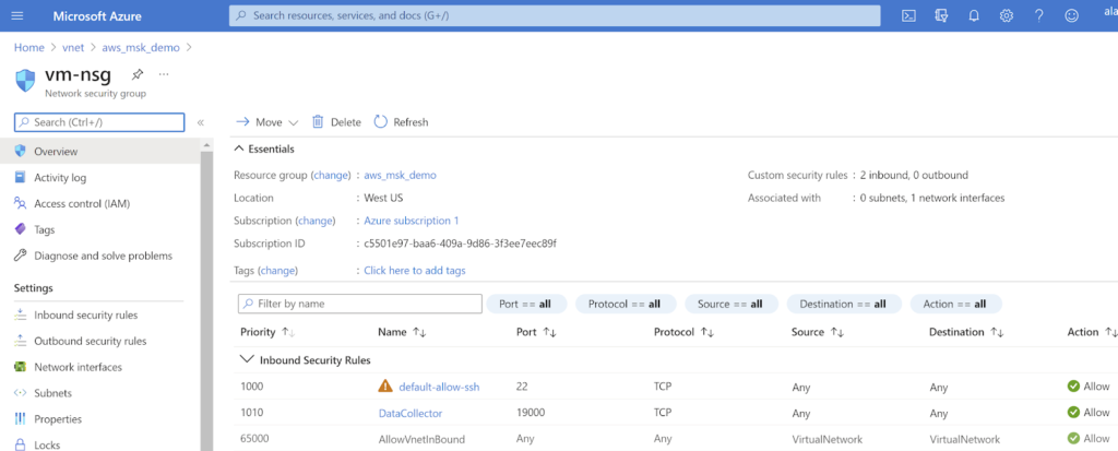
Figure 5 – Enabling applicable test traffic in the Azure VNET security group.
iperf3
- Install iperf3 on a VM in each platform using apt/yum.
| sudo apt -y install iperf3 |
Pipeline software
To install the pipeline software:
- SSH into VM
- Install docker and run a bespoke setup of StreamSets Datacollector:
- Runs StreamSets Datacollector
- Has Kafka libraries pre-installed
- Has pipelines pre-installed
| curl -fsSL https://get.docker.com -o get-docker.sh sudo sh get-docker.sh docker run -itd -p 19000:18630 alagalah/kafkatest |
- Connect to https://azure-vm-public-ip:19000
- Login using OAuth
- Navigate to Home using the House icon.
- Retrieve Kafka address from AWS MSK.
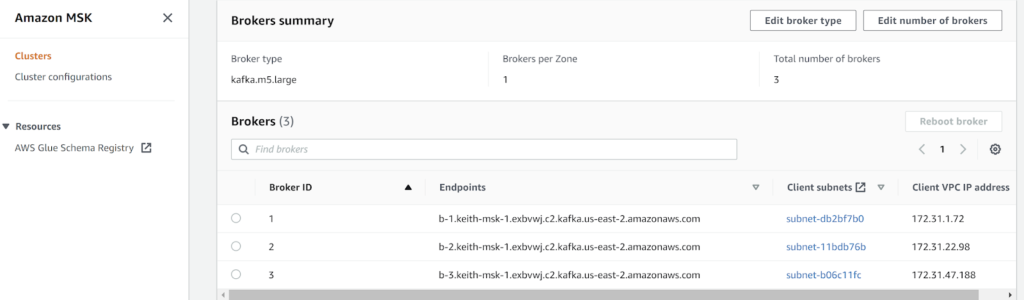
(To enable Client VPC IP address, select the “Preferences” cog directly above Brokers and enable the field using a toggle switch.)
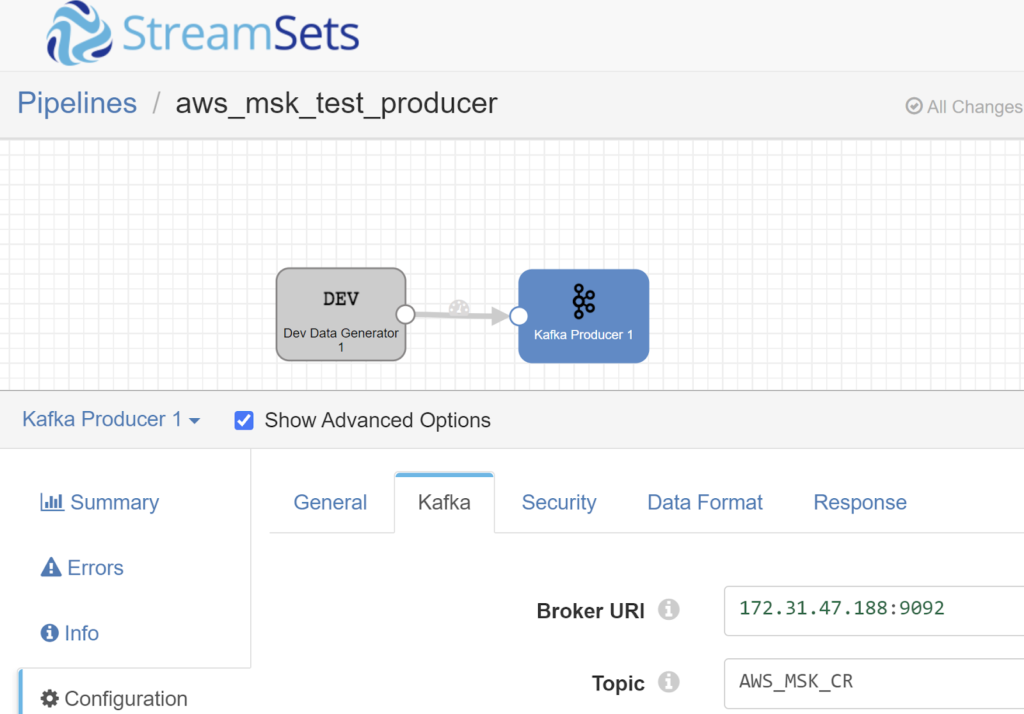
A single broker is used in this example, 172.31.47.188. This broker was chosen as it is on the same subnet as the AWS VM created in the AWS MSK tutorial above.
The private IP address is used to ensure that traffic is not “accidentally” going over the public Internet without using the site-to-site VPN OR alternatively, PacketFabric’s private Network as a Service (NaaS).
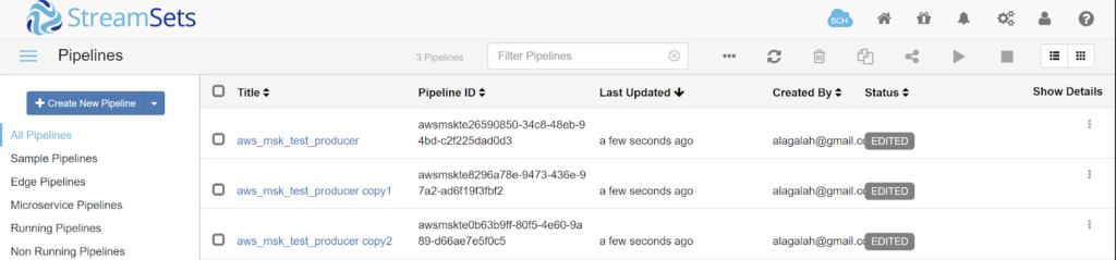
- Select each pipeline by using the hyperlink which is the pipeline name.
- Select the Kafka “stage” and enter the broker IP and the Kafka Topic created in the AWS MSK tutorial.
- In this case, 172.31.47.188 and AWS_MSK_CR.
Configure Case1: Site-to-site VPN networking
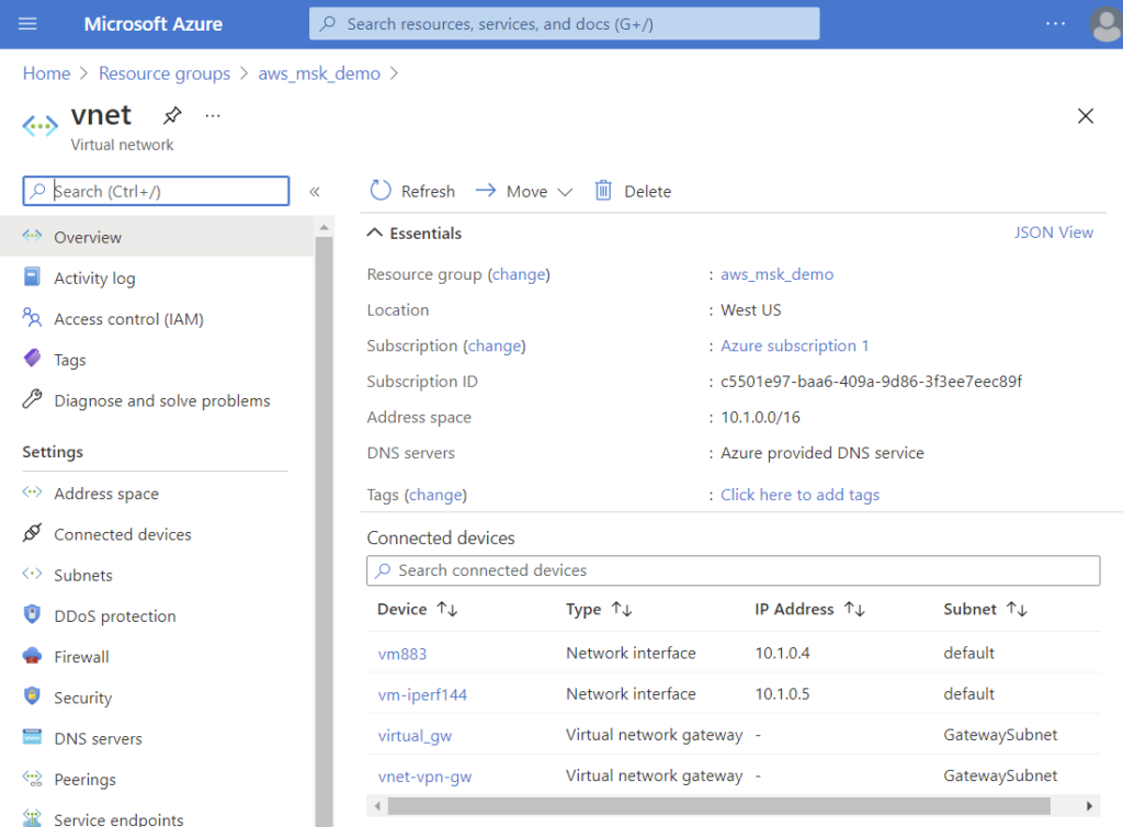
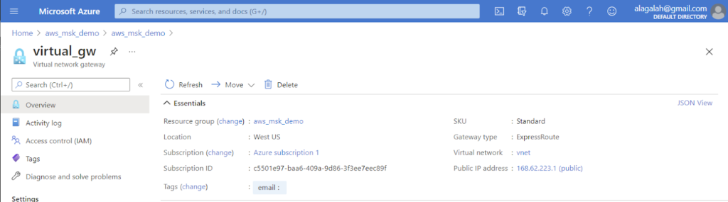
- In Azure, create a virtual network gateway.
- Create virtual network gateway
- Select a subnet from the existing CIDR block. For this example, theVNET uses 10.1.0.0/16, so we selected 10.1.1.0/24.
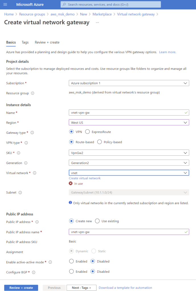
| IMPORTANT NOTES: After creation, note the public IP address, as this will be needed on the AWS side. It can be found in your Resource Group under “vnet-vpn-gw” if using the same names per example. |
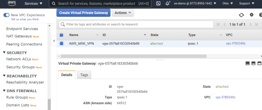
- Create an AWS Virtual Private Gateway from the VPC page in the AWS Console.
- Attach the VPN Gateway to a VPC by selecting Actions -> Attach to VPC
- Use the same VPC which is in use by the AWS MSK cluster
- Create a site-to-site VPN Connection from the same page.
- Use the Azure VNET prefix 10.1.0.0/16 in your static route.
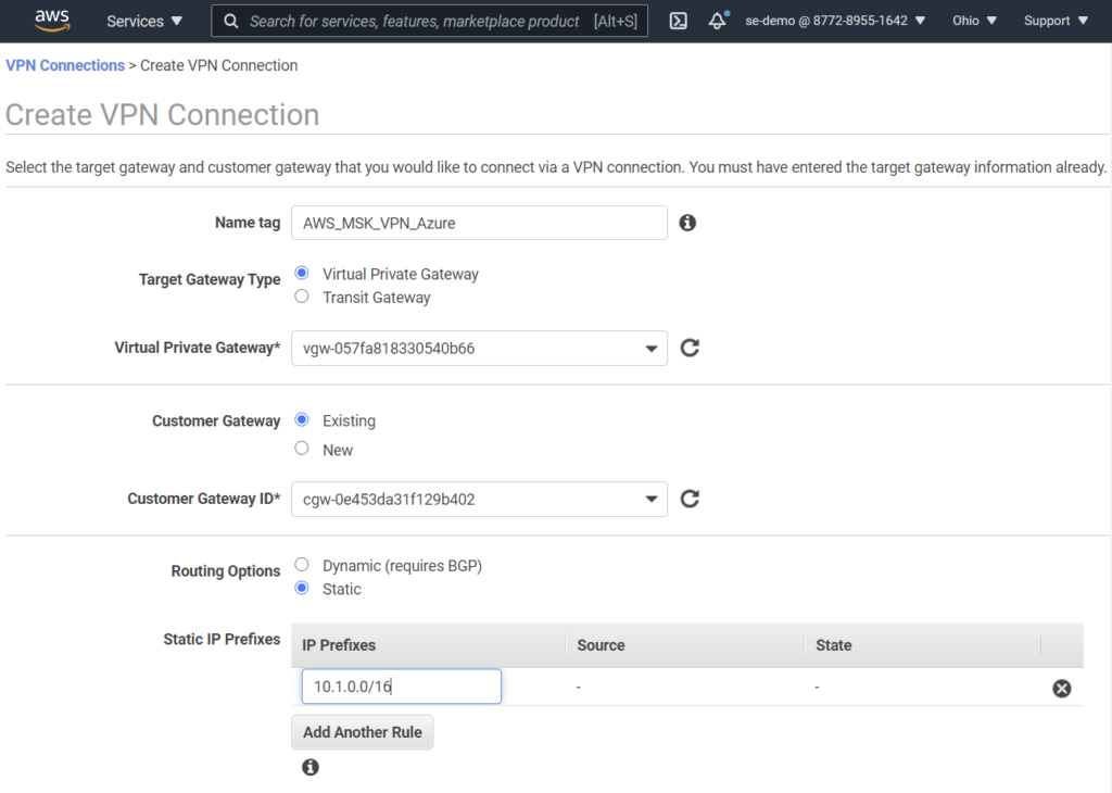
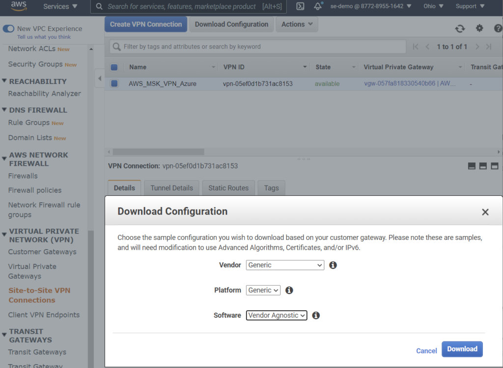
- Download configuration file using “Generic” options.
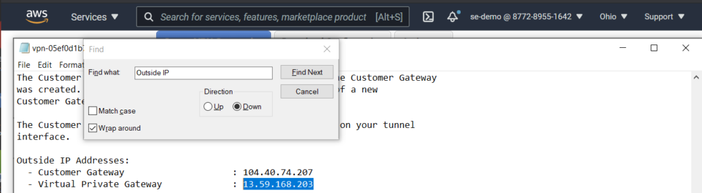
- Find the assigned outside IP address inside the configuration file. In this example, 13.59.168.203.
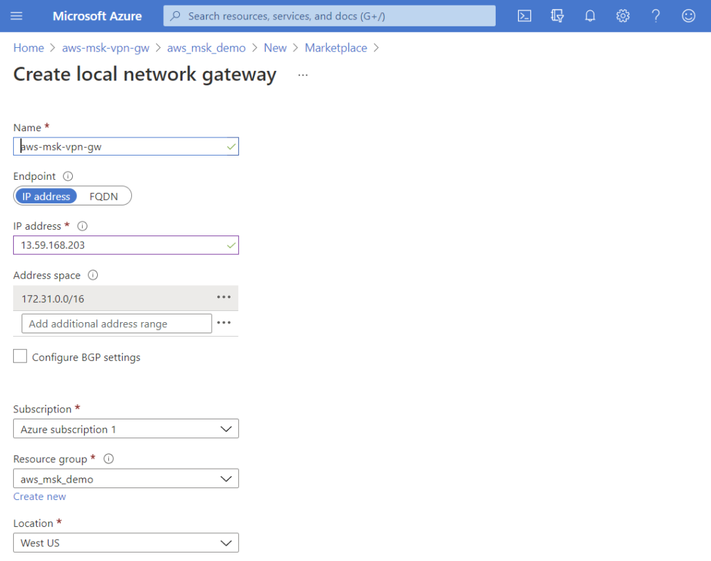
- Configure Azure Local Network Gateway.
- IP address is the public address from AWS site-to-site VPN configuration above.
- Address space is the IP prefix for AWS VPC. i.e. static route from Azure to AWS.
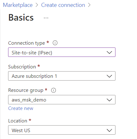
- Create Azure connection
- When prompted, select the local network gateway and virtual network gateway that was just created.
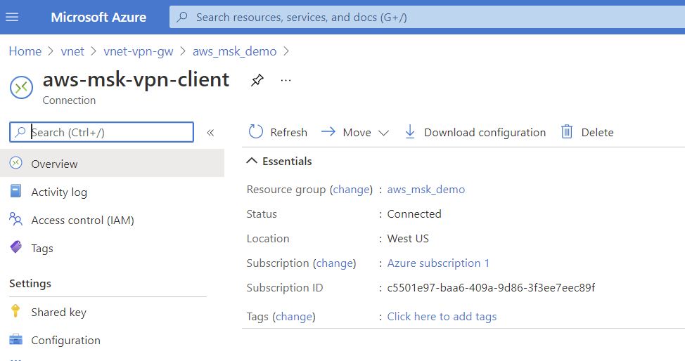
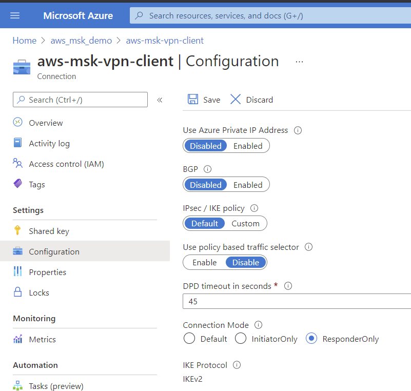
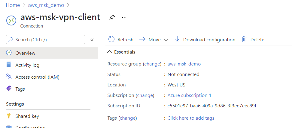
- Validate connection is established in Azure.
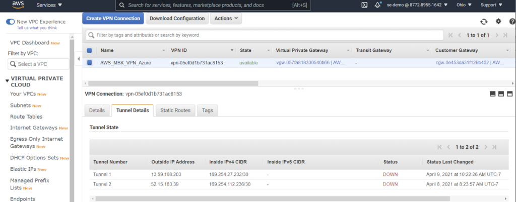
- Validate connection and routing in AWS
- Only one tunnel was used for this experiment. Please follow AWS recommendations in production.
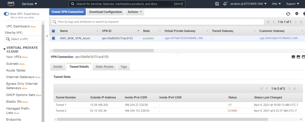
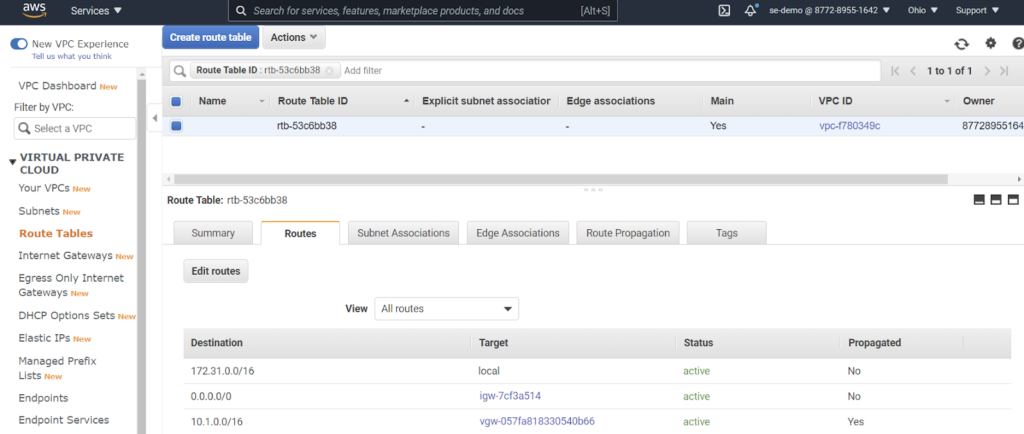
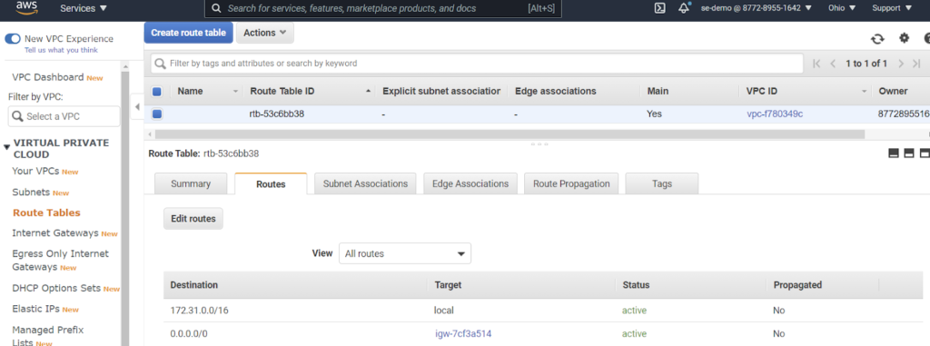
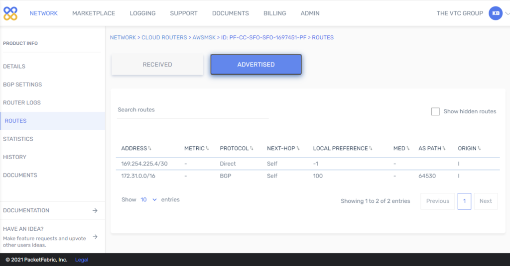
- Check AWS and Azure routing tables for respective VPCs. We expect the 10.1.0.0/16 route in AWS (learned from Azure peer) and 172.31.0.0/16 in Azure (learned from the AWS peer.
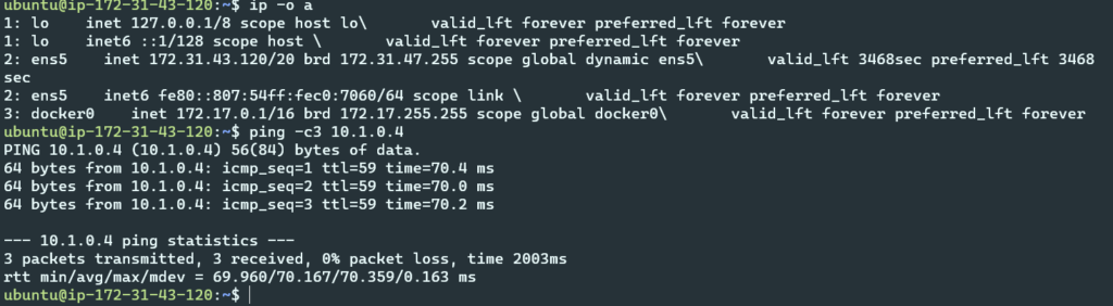
- Assuming changes outlined in “Configuration – Install and configure test tools” have been completed, Azure VM to AWS VM should be allowed and a ping will pass from private IP address to private IP address.
- Azure VM
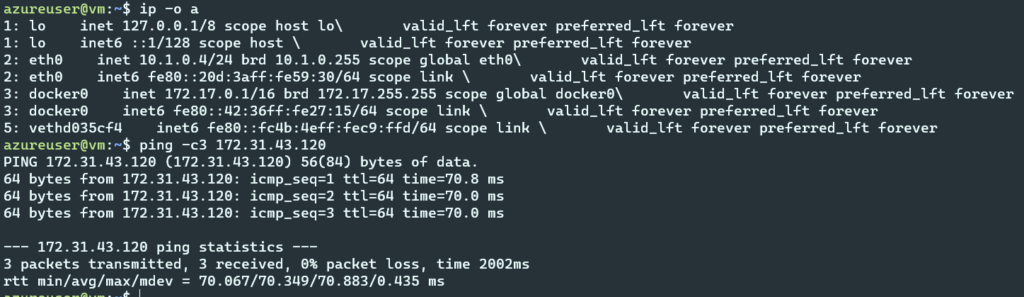
- AWS VM
- Note 10.1.0.0/16 static route not in AWS VPC routing table
- Run tests per Test data pipeline (jump to later section in paper).
Configure Case2: PacketFabric Virtual Cloud Router Networking
In this section, we have linked to PacketFabric Virtual Cloud Router processes to save space. The figures shown are the results of each step.
- From the Packetfabric portal, create a Virtual Cloud Router. (https://docs.packetfabric.com/cr/mgmt/create/ ).
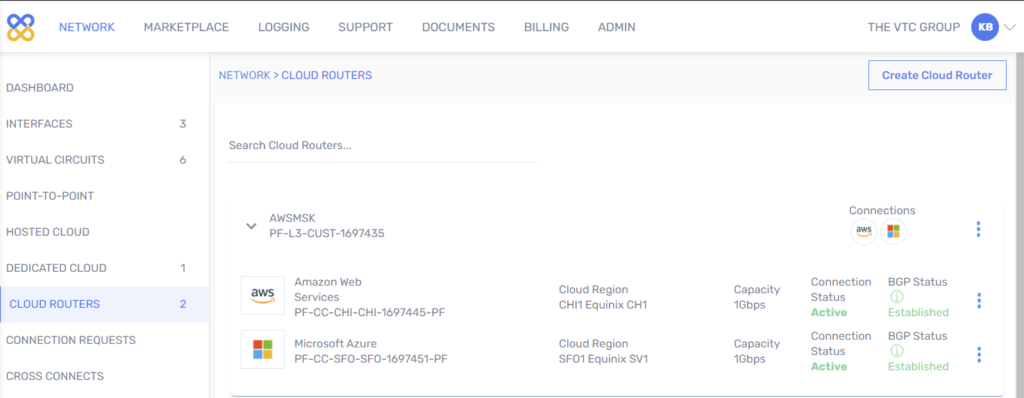
- Create Virtual Cloud Router AWS connection.
Process overview:
The basic steps to adding an AWS connection to a PacketFabric Distributed Virtual Cloud Router are as follows:1.1
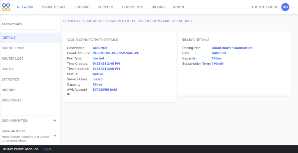
1. From the PacketFabric side: Create a cloud connection.
- After following the steps, the portal shows:
2. From the AWS side: Accept the connection.
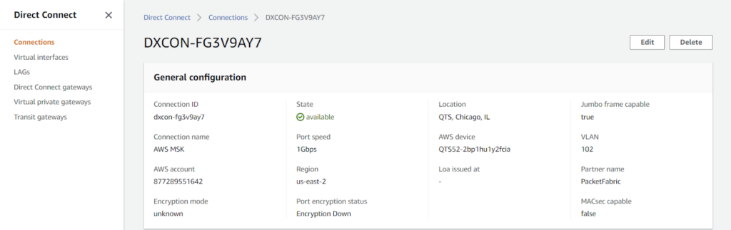
3. From the AWS side: Create a gateway.
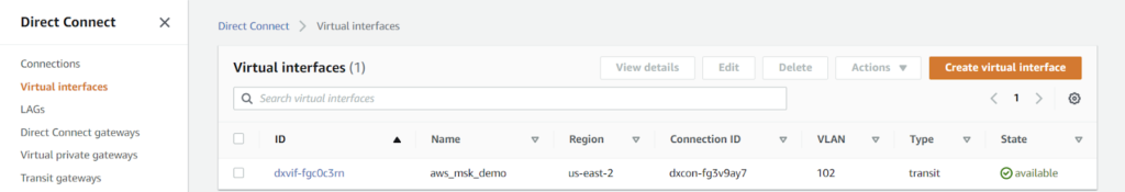
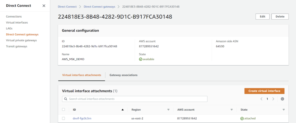
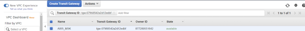
4. From the AWS side: Create and attach a VIF.
- Specifically, a Transit VIF is used
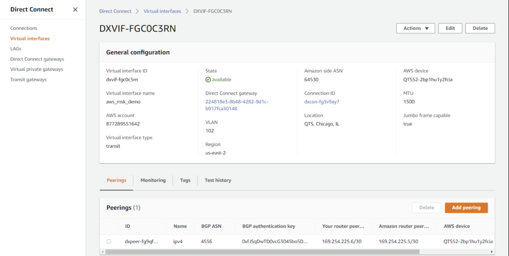
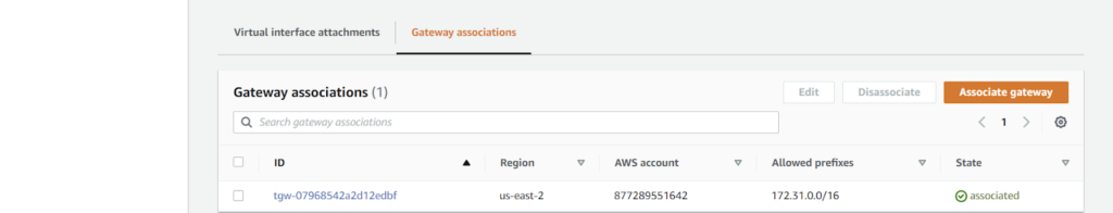
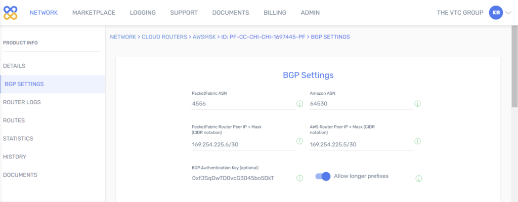
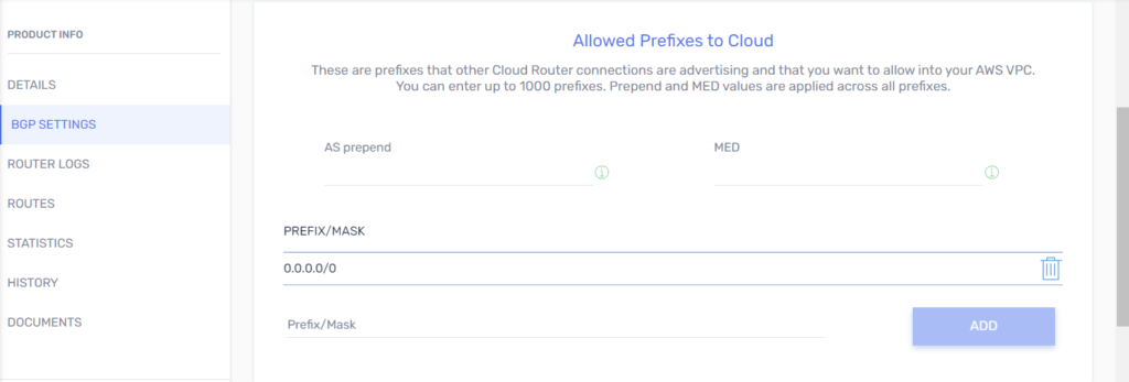
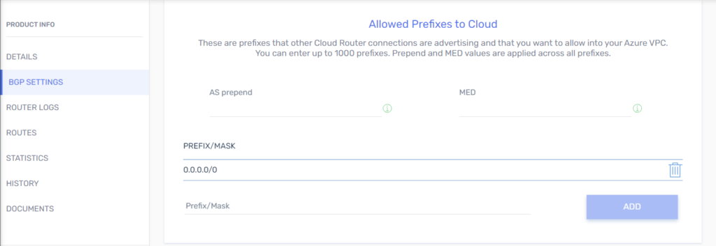
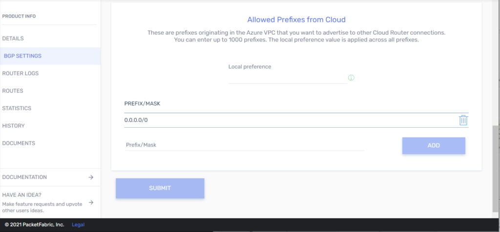
5. From the PacketFabric side: Configure BGP.
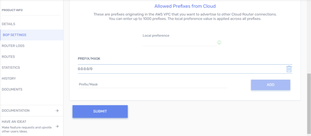
- Add an Azure ExpressRoute Connection to a Virtual Cloud Router
Process overview
The basic steps to adding an Azure connection to a PacketFabric Virtual Cloud Router are as follows:
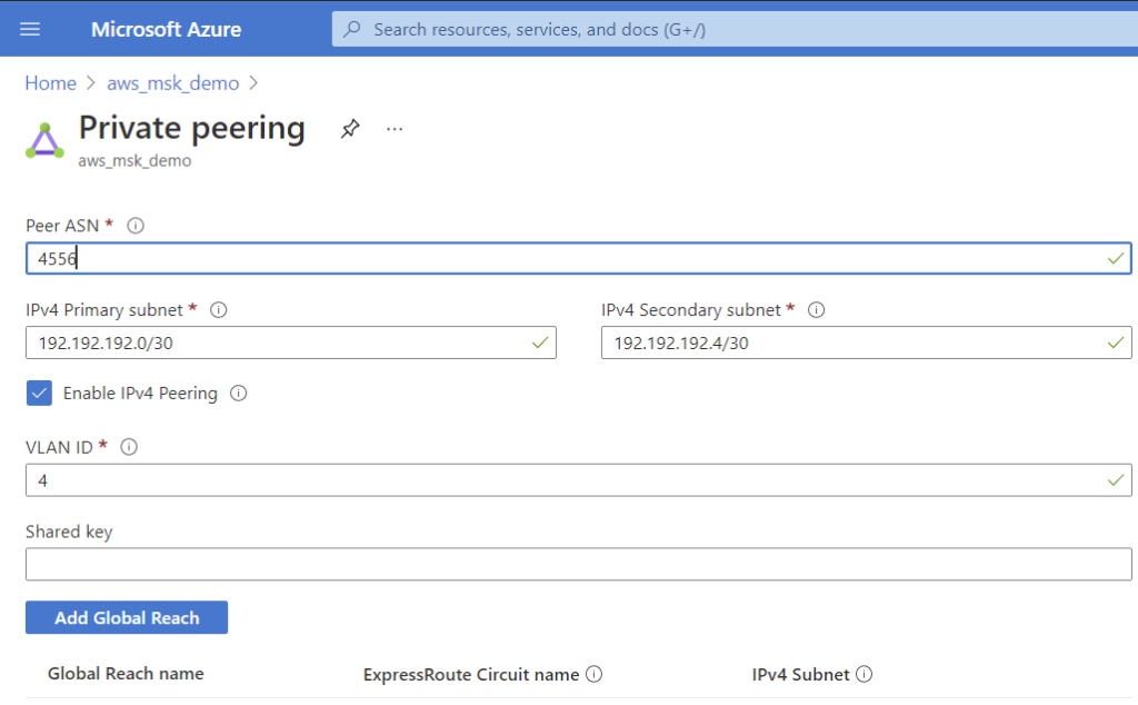
1. From the Microsoft side: Create an ExpressRoute circuit in the Azure Console.
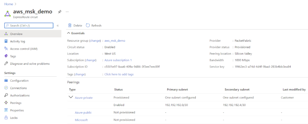
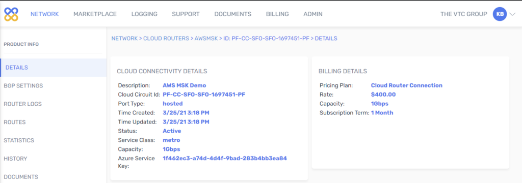
2. From the PacketFabric side: Create a Virtual Cloud Router connection.
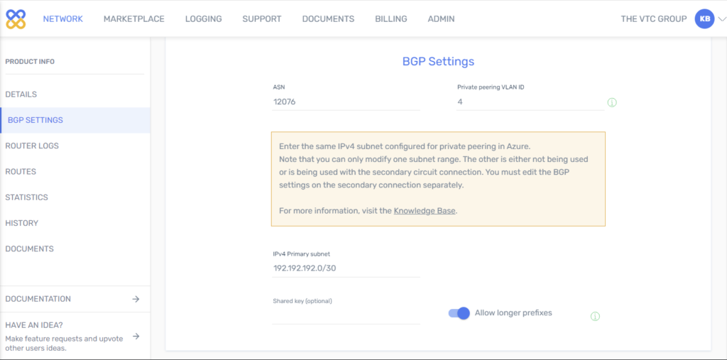
3. From both sides: Configure BGP.
4. From the Microsoft side: Create a virtual network gateway for ExpressRoute.
5. From the Microsoft side: Link a virtual network gateway to the ExpressRoute circuit.
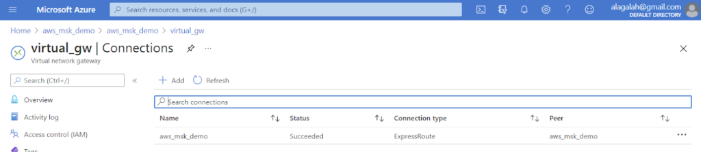
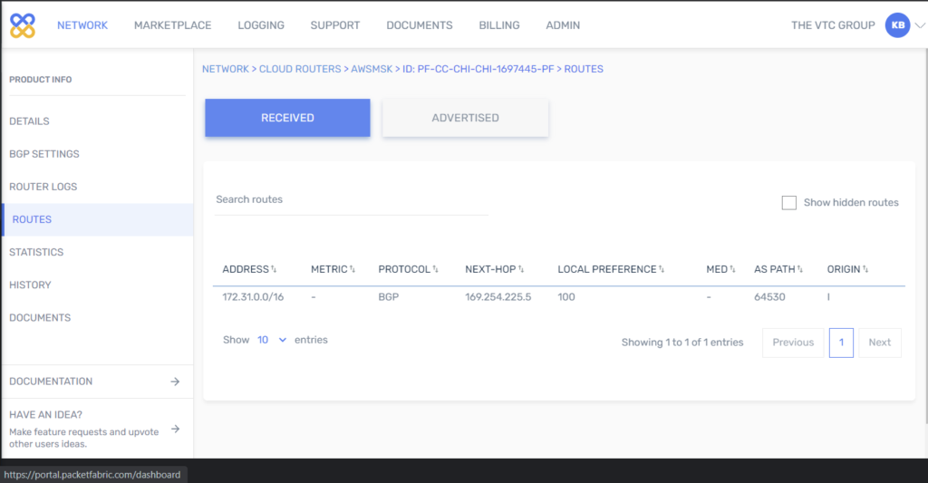
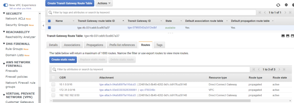
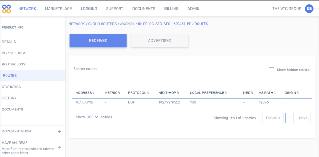
- Check routing.

- Run tests from Test data pipeline
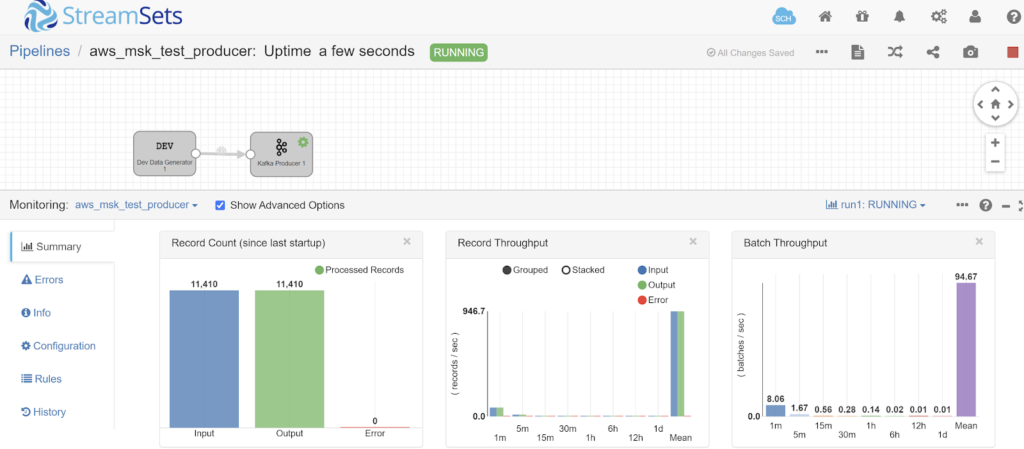
Test data pipeline
To generate transactional workload, a simple ETL pipeline is used. The open-source ETL software, StreamSets Datacollector, is used for this purpose.
The pipeline:
- generates records and sends to AWS MSK via Kafka Producer
- Kafka Consumer reads from AWS MSK and sends to Trash
iperf3
- Run one iperf3 instance per vCPU available on server (AWS) and client (Azure) VMs
| # AWS server 172.31.43.120 sudo iperf3 -s -p 3000 & sudo iperf3 -s -p 3001 & sudo iperf3 -s -p 3002 & sudo iperf3 -s -p 3003 & sudo iperf3 -s -p 3004 & sudo iperf3 -s -p 3005 & sudo iperf3 -s -p 3006 & sudo iperf3 -s -p 3007 & # Azure client sudo iperf3 -c 172.31.43.120 -i 1 -t 3600 -p 3000 -b 1000000000000 & sudo iperf3 -c 172.31.43.120 -i 1 -t 3600 -p 3001 -b 1000000000000 & sudo iperf3 -c 172.31.43.120 -i 1 -t 3600 -p 3002 -b 1000000000000 & sudo iperf3 -c 172.31.43.120 -i 1 -t 3600 -p 3003 -b 1000000000000 & sudo iperf3 -c 172.31.43.120 -i 1 -t 3600 -p 3004 -b 1000000000000 & sudo iperf3 -c 172.31.43.120 -i 1 -t 3600 -p 3005 -b 1000000000000 & sudo iperf3 -c 172.31.43.120 -i 1 -t 3600 -p 3006 -b 1000000000000 & sudo iperf3 -c 172.31.43.120 -i 1 -t 3600 -p 3007 -b 1000000000000 & |
Pipeline software
- From “Home”, select all 3 pipelines and click the “Play” icon to start the pipelines.
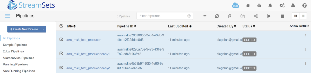
- Select a pipeline to see the Summary statistics